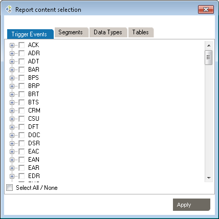
This method is useful when you have a large volume of message types and trigger events to document, based on a specific HL7 version. If your specification is more limited, consider building a profile from individual message elements.
You will need to edit the profile to reflect the specification. Go to Editing a Profile to learn more.
You can also build a profile from individual message elements. This method is useful when the specification you are building is limited to a small subset of an HL7 version and when customization is extensive
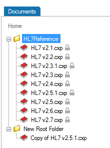
You can add a trigger event or message type from one of the HL7 references or from a previously built profile.
In the Documents pane, double-click on the profile you want to build out.
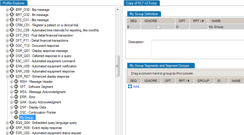
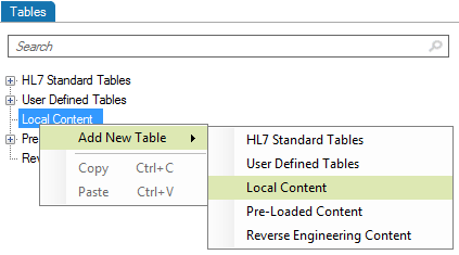
In the Profile Explorer, right-click on the first node.
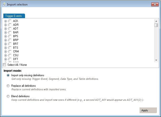
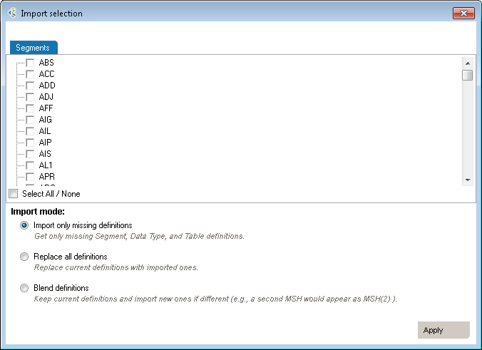
| Mode | Why Choose This Option | Action | Example |
| Import only missing definitions | Choose this if you only want to import element that don’t already exists in your profile | This will import definitions that are not present in the current profile and all referenced elements. | Your profile doesn’t have a ADT_A01 trigger event you’d like to add from HL7 v2.6. |
| Replace all definitions | Choose this if you need to replace all existing definitions with the imported definitions. | Replace existing elements by imported elements. This means that you’ll overwrite current definitions. The segment definition will change to the imported definition. | Your profile has an ADT_A08 definition that would like to replace by the one from v2.6. |
| Blend definitions | Choose this if you need to import a definition from another profile, but also need to keep all definitions from both profiles. | This will import all selected and referenced definitions and will duplicated all elements that are different. | Your profile has a custom ADT_AZZ definition from one source system. A second source system uses a different definition. You need to code an interface for both definitions. |
You can add an event or message without segments, fields, associated data types, or tables. These elements must be defined later. Use this method when the event to be specified has not been formally defined in the HL7 standard.
In the Document pane, double-click on the profile you want to edit. Right-click on the first node and select Add, Trigger Event. A new trigger event is added.

Rename the trigger event and add a description.
Once you have added trigger events, you can edit segments, fields, and data types within your profile. See Editing a Profile for more information.
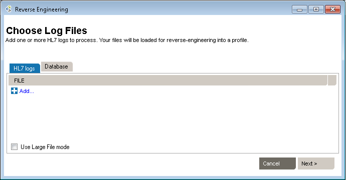
The Reverse Engineering tool enables you to create a profile from an HL7 log (or HL7 message file). A profile (also known as a specification or message definition) documents the message structure and content, including the use of Z-segments and custom data types.
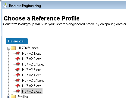
To open the Reverse-Engineering tool, click PROFILE v2, New, With Reverse-engineerer Wizard... The tool opens to Choose Log Files.
Then click Next to go to the next step. You can also load messages by querying a database.
To begin building a profile based on the messages you just loaded, the software needs an established profile to compare against. Select a profile that most closely matches your messages, then click Next. (Note: the software picks up on the HL7 version specified in your messages, but you are free to choose another reference).
The messages load.
(If they load too slowly, you can click the Cancel button in the Loading dialog box and only messages that have loaded thus far will appear.)
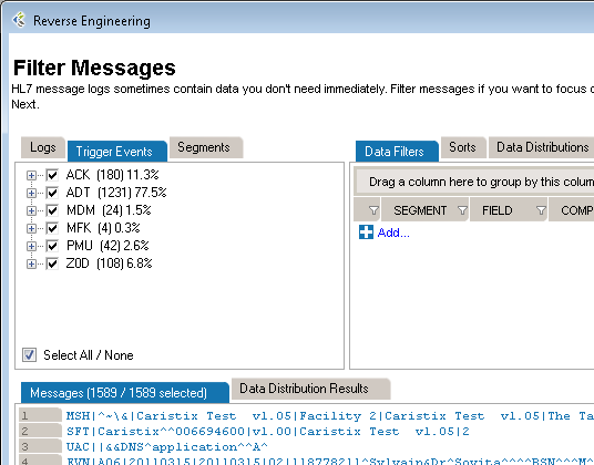
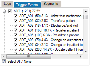
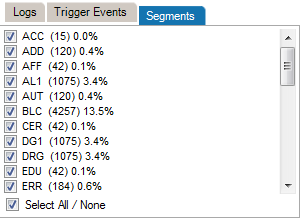
If there are files, events, segments, or other data elements you don’t require for the profile, filter them out in this step (read Filter an HL7 Log to learn more), then click Next to go to the next step. To reverse-engineer all messages without filtering, simply click Next.
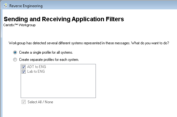
This step is optional. The software will detect all sending and receiving applications present in the messages. If only one combination is detected, this step is skipped.
You have two options here. You can either generate a single profile combining all applications represented in the message file, or you can create separate profiles for each sending and receiving application combination. The second option offers you the possibility to choose specific combinations; it will also run the next 5 steps consecutively for all selected combinations.
The software sets up the reference profile and messages you selected. Once the processing is complete, simply click Next to continue, as specified on-screen.
Choose between Basic and Advanced field analysis.
This choice lets you analyze fields and data values and assign known data types. If Conformance finds data values and fields that do not match known data types, an new data type will be assigned. You can manually edit the data types later, when the reverse-engineering profile appears in the Library.
Select Basic Field Analysis if:
you are not sure that data types are important to your analysis.
you want to speed up your analysis and focus on identifying details in other message elements such as events and segments.
This choice lets you fully analyze fields and data values. Data values and fields that do not match expected data types will be flagged. You will have the opportunity to either create custom data types to handle non-HL7-compliant data, or assign an existing data type.
Select Advanced Field Analysis if:
you need complete data type analysis for your interfacing project
you are comfortable creating new data types for further analysis
This section allows you to set more specific options for data and field analysis.
Once you make your selection in Step 2, click Next.
The software reads through the messages and segments to begin building the profile. When processing is complete, click Next to continue, as specified on-screen.
This step creates the field structure in your profile, assigns data values to user tables, and associates data types to fields and values.
If you selected Basic Field Analysis in Step 3, Basic Mode appears in Step 4. Workgroup processes the fields and data types automatically. When the processing is finished, click Next.
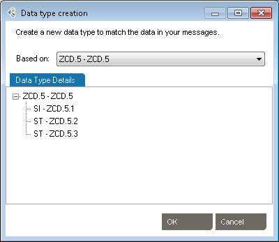
If you selected Advanced Field Analysis in Step 3, Advanced Mode appears in Step 4. Workgroup analyzes each segment for data values and fields that do not match expected data types. In other words, the software automatically performs a conformance check. When non-compliant elements are flagged, the software automatically suggests a data type and field structure. You can accept the suggestion, assign another data type, or create a new data type to handle the non-compliant values and fields.
Edit as needed to reflect maximum field length
Specify usage.
This tab provides a list of the data values that were flagged as non-compliant, as well as how many times they were found in the messages.
When processing is complete, click Next to continue.
This step will collect analyze the message flows in your logs (if you select this option at step 2). These message flows will be stored into the profile and available for future uses, to generate test messages for example.
This is the final step in the Reverse-Engineering wizard. Specify a folder to save the profile to or browse your computer to save it locally. Name the profile. And provide a description if needed. Click Save to close the Reverse-Engineering wizard and go to the Documents pane. (If multiple Sending and Receiving Applications were selected, the wizard will start a new analysis on Step 1)
There are two ways to add segments, depending on your needs. You can either add a segment defined in the profile you’re working on, or add one from a different profile.
Start here:
To create a new Segment definition, click on Add Segment, New. A new Segment definition appears at the bottom of the list.
You can also create a copy of an existing Segment definition by right-clicking on the source definition, select Copy and then right-click again and select Paste. A new Segment definition appears at the bottom of the list.
| Mode | Why Choose This Option | Action | Example |
| Import only missing definitions | Choose this if you only want to import element that don’t already exist in your profile. | This will import definitions that are not present in the current profile and all referenced elements. | Your profile doesn’t have a PID segment you’d like to add from HL7 v2.6. |
| Replace all definitions | Choose this if you need to replace all existing definitions with the imported definitions. | Replace existing elements with imported elements. This means that you’ll overwrite current definitions. The segment definition will change to the imported definition. | Your profile has an XPN definition that you would like to replace with the one from v2.6. |
| Blend definitions | Choose this if you need to import a definition from another profile, but also need to keep all definitions from both profiles. | This will import all selected and referenced definitions and will duplicate all elements that are different. | Your profile has a custom ZOD definition from one source system. A second source system uses a different definition. You need to code an interface for both definitions. |
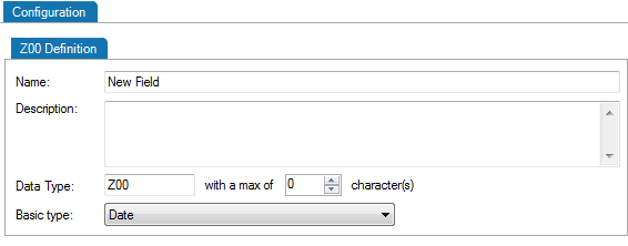
This is useful when you need to add a new data type for a Z-segment or a custom field.
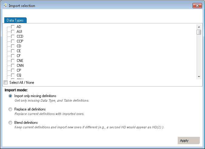
| Mode | Why Choose This Option | Action | Example |
| Import only missing definitions | Choose this if you only want to import elements that don’t already exist in your profile. | This will import definitions that are not present in the current profile and all referenced elements. | Your profile doesn’t have a TS (time-stamp) data type you’d like to add from HL7 v2.6. |
| Replace all definitions | Choose this if you need to replace all existing definitions with the imported definitions. | Replace existing elements with imported elements. This means that you’ll overwrite current definitions. The segment definition will change to the imported definition. | Your profile has an HD definition that would like to replace by the one from v2.6. |
| Blend definitions | Choose this if you need to import a definition from another profile, but also keep all definitions from both profiles. | This will import all selected and referenced definitions and will duplicated all elements that are different. | Your profile has a custom TS definition from one source system. A second source system uses a different definition. You need to code an interface for both definitions. |
This is useful when you need to add a new table for a Z-segment.

Edit segments and fields, so you capture the data elements pertinent to your specification. Due to the nature of the HL7 standard (HL7 is object-oriented), any changes made are global changes and affect the entire profile.
There are two ways to access segments and fields:
Click the “+” sign to expand a message, then edit the segment.

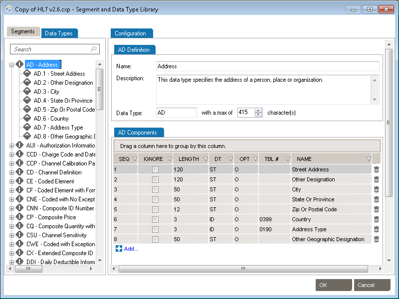
Right-click a message, and select Segment... A separate window displays the Segment Library. Expand the segment you wish to edit by clicking the plus sign.
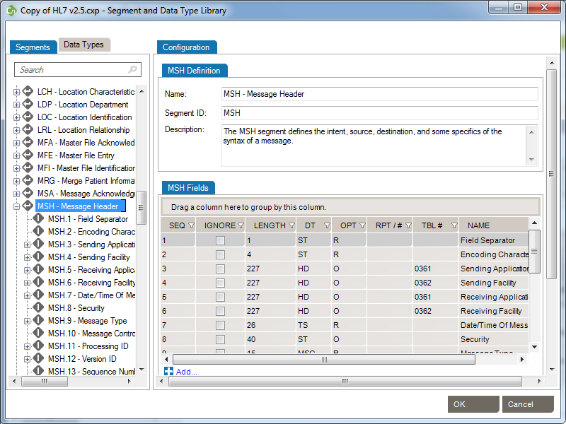
To edit each field or individual component, click on the title. Under the Configuration tab, make the changes to each field attribute.
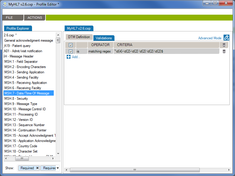
From the Validations tab, you can configure a set of rules that validate message content (data) is conform.
In the following example, the rule will validate (and raise conformance gaps) if the MSH.7 of a message does not conform to the format “yyyy-mm-dd hh:MM:ss”
Generate profile reports of an interface specification:
Note: You can also synch your profile. This feature allows a user to update the Word document directly and synchronize the profile library with the upload document content.
Complex types describe the permitted content of an element, including its element and text children and its attributes. A complex type definition consists of a set of attribute uses and a content model. The types of content model include element-only content, in which no text may appear (other than whitespace, or text enclosed by a child element); simple content, in which text is allowed but child elements are not; empty content, in which neither text nor child elements are allowed; and mixed content, which permits both elements and text to appear. A complex type can be derived from another complex type by restriction (disallowing some elements, attributes, or values that the base type permits) or by extension (allowing additional attributes and elements to appear).
XML Type Editor in Workgroup works as follows:
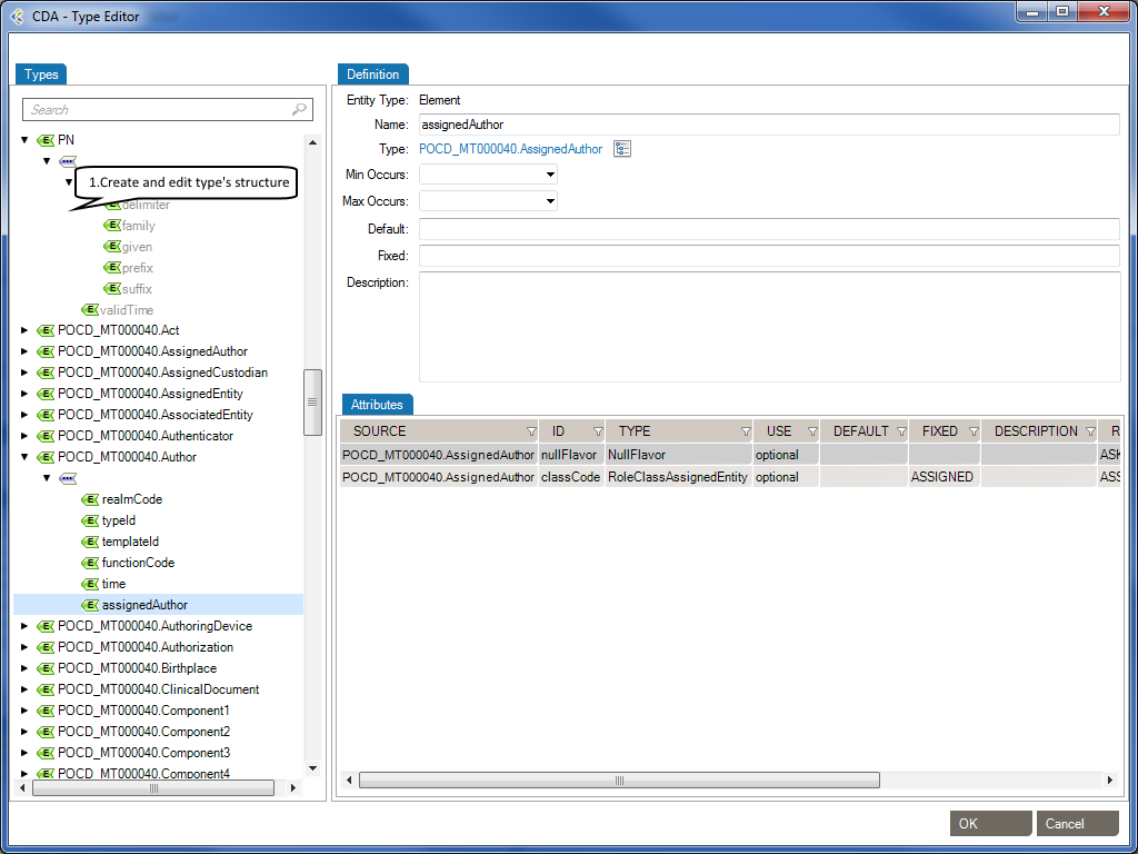
The Types tab describes the structure of a type. You can add the following elements to the structure of a type.
| Element: | A complex element is an XML element that contains other elements and/or attributes. |
| Element Group: | The group element is used to define a group of elements to be used in complex type definitions. |
| Sequence: | The sequence element specifies that the child elements must appear in a sequence. Each child element can occur from 0 to any number of times. |
| Choice: | XML Schema choice element allows only one of the elements contained in the declaration to be present within the containing element. |
The Definition tab describes an element’s properties.
| Name: | Specifies a name for the element. This attribute is required if the parent element is the schema element. |
| Type: | Optional. Specifies either the name of a built-in data type, or the name of a simpleType or complexType element. |
| Min Occurs: | Optional. Specifies the minimum number of times this element can occur in the parent element. |
| Min Occurs: | The value can be any number >= 0. Default value is 1. This attribute cannot be used if the parent element . |
| Default: | Optional. Specifies a default value for the element (can only be used if the element’s content is a simple type or text only). |
| Fixed: | Optional. Specifies a fixed value for the element (can only be used if the element’s content is a simple type or text only). |
| Description: | Optional. Describes the element in natural language. |
The Attributes tab describes an element’s attributes.
| SOURCE: | Specifies the attribute’s owner. |
| ID: | Specifies a unique ID for the attribute. |
| TYPE: | Optional. Specifies a built-in data type or a simple type. The type attribute can only be present when the content does not contain a simpleType element. |
| USE: | Optional. Specifies how the attribute is used. Can be one of the following values:
|
| DEFAULT: | Optional. Specifies a default value for the attribute. Default and fixed attributes cannot both be present. |
| FIXED: | Optional. Specifies a fixed value for the attribute. Default and fixed attributes cannot both be present. |
| DESCRIPTION: | Optional. Describes the attribute in a natural language. |
| RESTRICTED VALUES: | Optional. Restrictions are used to define acceptable values for XML attributes. |
Schematron is a rule-based validation language for making assertions about the presence or absence of patterns in XML trees. It is a structural schema language expressed in XML using a small number of elements and XPath.
Schematron is capable of expressing constraints in ways that other XML schema languages like XML Schema and DTD cannot. For example, it can require that the content of an element be controlled by one of its siblings. Or it can request or require that the root element, regardless of what element that is, must have specific attributes. Schematron can also specify required relationships between multiple XML files.
Constraints and content rules may be associated with “plain-English” validation error messages, allowing translation of numeric Schematron error codes into meaningful user error messages.
XML Schematron Editor in Workgroup works as follows:
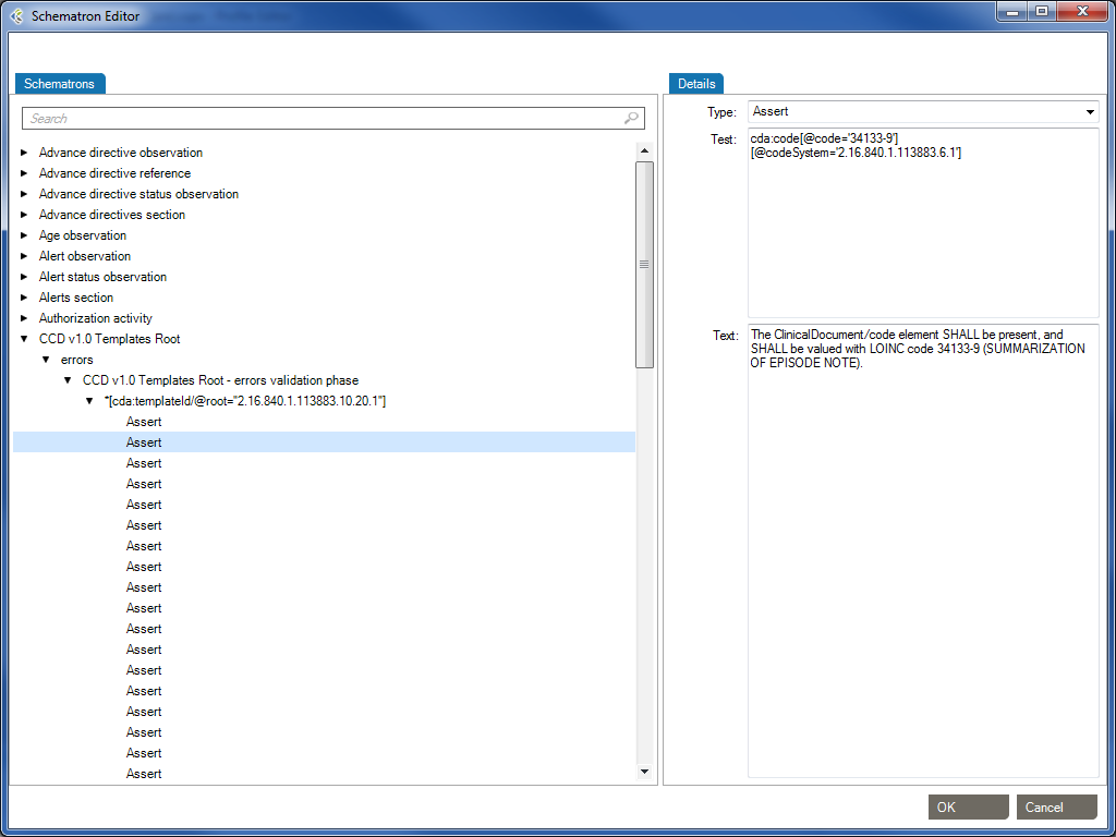
The Schematron schema language differs from most other XML schema languages in that it is a rule-based language that uses path expressions instead of grammars. This means that instead of creating a grammar for an XML document, a Schematron schema makes assertions that are applied to a specific context within the document. If the assertion fails, a diagnostic message that is supplied by the author of the schema can be displayed.
One advantages of a rule-based approach is that in many cases modifying the wanted constraint written in plain English can easily create the Schematron rules. For example, a simple content model can be written like this: “The Person element should in the XML instance document have an attribute Title and contain the elements Name and Gender in that order. If the value of the Title attribute is ‘Mr’ the value of the Gender element must be ‘Male’.”
In this sentence the context in which the assertions should be applied is clearly stated as the Person element while there are four different assertions:
Person) should have an attribute TitleName and GenderName should appear before the child element GenderTitle has the value ‘Mr’, the element Gender must have the value ‘Male’In order to implement the path expressions used in the rules in Schematron, XPath is used with various extensions provided by XSLT.
It has already been mentioned that Schematron makes various assertions based on a specific context in a document. Both the assertions and the context make up two of the four layers in Schematron’s fixed four-layer hierarchy:
The bottom layer in the hierarchy is the assertions, which are used to specify the constraints that should be checked within a specific context of the XML instance document. In a Schematron schema, the typical element used to define assertions is assert. The assert element has a test attribute, which is an XSLT pattern. In the preceding example, there was four assertions made on the document in order to specify the content model, namely:
Person) should have an attribute TitleName and GenderName should appear before the child element GenderTitle has the value ‘Mr’, the element Gender must have the value ‘Male’Written using Schematron assertions this would be expressed as
| Type | Test | Text |
|---|---|---|
| Assert | @Title | The element Person must have a Title attribute. |
| Assert | count(*) = 2 and count(Name) = 1 and count(Gender)= 1 | The element Person should have the child elements Name and Gender. |
| Assert | *[1] = Name | The element Name must appear before element Gender. |
| Assert | (@Title = 'Mr' and Gender = 'Male') or @Title != 'Mr' | If the Title is “Mr” then the gender of the person must be “Male”. |
If you are familiar with XPath, these assertions are easy to understand, but even for people with limited experience using XPath they are rather straightforward. The first assertion simply tests for the occurrence of an attribute Title. The second assertion tests that the total number of children is equal to 2 and that there is one Name element and one Gender element. The third assertion tests that the first child element is Name, and the last assertion tests that if the person’s title is ‘Mr’, the gender of the person must be ‘Male’.
If the condition in the test attribute is not fulfilled, the content of the assertion element is displayed to the user.
Each of these assertions has a condition that is evaluated, but the assertion does not define where in the XML instance document this condition should be checked. For example, the first assertion tests for the occurrence of the attribute Title, but it is not specified on which element in the XML instance document this assertion is applied. The next layer in the hierarchy, the rules, specifies the location of the contexts of assertions.
The Assert type element is used to tag positive assertions about a document.
The Report type is used to tag negative assertions about a document.
The rules in Schematron are declared by using the rule element, which has a context attribute. The value of the context attribute must match an XPath Expression that is used to select one or more nodes in the document. Like the name suggests, the context attribute is used to specify the context in the XML instance document where the assertions should be applied. In the previous example the context was specified to be the Person element, and a Schematron rule with the Person element as context would simply be
| Id | Abstract | Context |
|---|---|---|
| False | Person |
Since the rules are used to group all assertions together that share the same context, the rules are designed so that the assertions are declared as children of the rule element. For the previous example, this means that the complete Schematron rule would be
The element Person must have a Title attribute.
The element Person should have the child elements Name and Gender.
The element Name must appear before element Age.
If the Title is "Mr" then the gender of the person must be "Male".
This means that all the assertions in the rule will be tested on every Person element in the XML instance document. If the context is not all the Person elements, it is easy to change the XPath location path to define a more restricted context. The value Database/Person, for example, sets the context to be all the Person elements that have the element Database as its parent.
The third layer in the Schematron hierarchy is the pattern, declared using the pattern element, which is used to group together different rules. The pattern element also has a name attribute that will be displayed in the output when the pattern is checked. For the preceding assertions, you could have two patterns: one for checking the structure and another for checking the co-occurrence constraint. Since patterns group different rules together, Schematron is designed so that rules are declared as children of the pattern element. This means that the previous example, using the two patterns, would look like
The element Person must have a Title attribute.
The element Person should have the child elements Name and Gender.
The element Name must appear before element Age.
If the Title is "Mr" then the gender of the person must be "Male".
The name of the pattern will always be displayed in the output, regardless of whether the assertions fail or succeed. If the assertion fails, the output will also contain the content of the assertion element. However, there is also additional information displayed together with the assertion text to help you locate the source of the failed assertion. For example, if the co-occurrence constraint above was violated by having Title=’Mr’ and Gender=’Female’ then the following diagnostic would be generated by Schematron:
From pattern "Check structure":From pattern "Check co-occurrence constraints":
Assertion fails: "If the Title is "Mr" then the gender of the person must be "Male"."
at /Person[1] ...</>
The pattern names are always displayed, while the assertion text is only displayed when the assertion fails. The additional information starts with an XPath expression that shows the location of the context element in the instance document (in this case the first Person element) and then on a new line the start tag of the context element is displayed.
The assertion to test the co-occurrence constraint is not trivial, and in fact this rule could be written in a simpler way by using an XPath predicate when selecting the context. Instead of having the context set to all Person elements, the co-occurrence constraint can be simplified by only specifying the context to be all the Person elements that have the attribute Title=’Mr’. If the rule was specified using this technique, the co-occurrence constraint could be described like this
If the Title is "Mr" then the gender of the person must be "Male".
By moving some of the logic from the assertion to the specification of the context, the complexity of the rule has been decreased. This technique is often very useful when writing Schematron schemas.
*[Reference: www.xml.com/pub/a/2003/11/12/schematron.html]
Gap Analysis Filters are used to remove irrelevant gaps. Each filter contains a set of preset options which will optimize the Gap Analysis detection process in order to show you only the “dangerous” gaps. A Gap Analysis Filter contains:
When you’ll start a new Gap Analysis, after selecting the profiles to compare, you will be asked to select a Gap Analysis Filter.
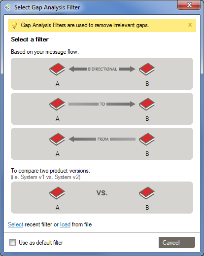
There are 4 pre-defined Filters that can be used.
This filter should be used when both systems exchange messages between each other.
This filter should be used when the first system sends messages to the second system.
This Filter should be used when the first system receives messages coming from the second system.
This filter should be used when you want to compare profiles representing the same system. Ex: Comparing reverse-engineered profiles coming from sample messages of your development and production environments.
While working with the Gap Analysis Workbench, you can edit computed attributes, options and difference filters. These can then be saved as a Custom Filter, which can be re-used for other Gap Analysis.
In the Gap Analysis Filter Selection window, you’ll be able to Select a “recent Gap Analysis Filter”, or Load a previously saved filter from your Library.
You’ll be able to set your choice of the default filter for your subsequent Gap Analysis and will not be asked to select a Gap Analysis filter again. Whenever you want, you may apply another Gap Analysis Filter in the Gap Analysis Workbench with “File > Gap Analysis Filter > Change Filter…“
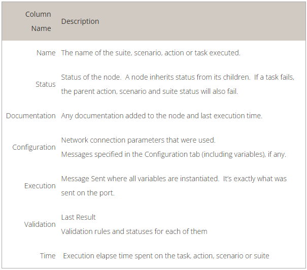
Here is a quick look of the Gap Analysis Workbench.
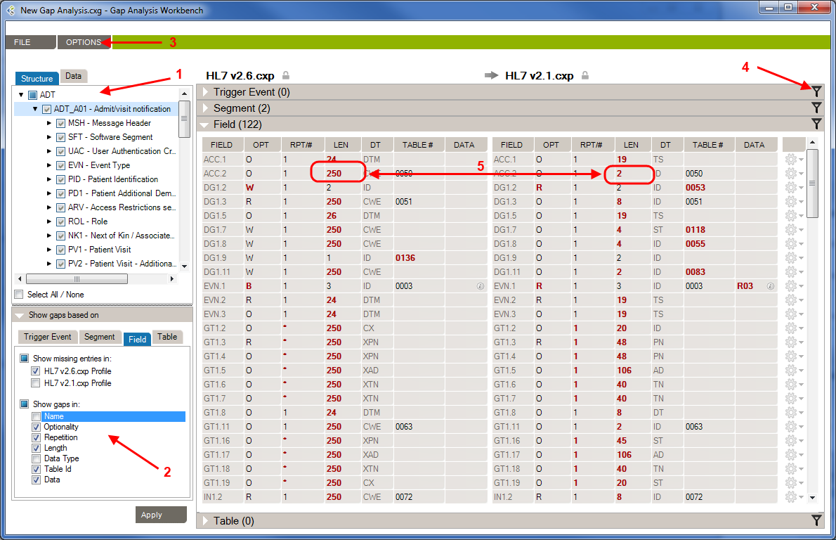
1- Structure/Data Element: In this section, you’ll choose which element from your profiles will be compared.
2- Attributes: In this section, you’ll choose which attributes, from the previously selected elements, will be compared.
3 – Options: In this menu, you’ll be able to set options to improve the accuracy of the Gap Analysis comparison process.
4- Differences Filters: Differences Filters are used to show differences that match some specific criteria. In other words, discard the differences that aren’t relevant to your analysis.
5 – Gap Analysis Results: In this section, you will see all differences between the selected elements of your profiles, based on your Gap Analysis filter (Attribute, Options, Differences Filters).
By default, when you first see the Gap Analysis Workbench, nothing is selected. When you run a Gap Analysis, you select the data elements that matter to your interface.
The Gap Analysis Workbench is split in 2 sections:
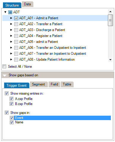
At the top of the Criteria Section, you’ll see the list of the messages, segments, fields, and data tables that are contained in the 2 profiles (or profile and messages) you are comparing. Select an element to include it in the Gap Analysis.
*(Steps prior to these examples)
**Choose HL7 v2.6 as the Reference and HL7 v2.1 as the Compared Profile.
By default, comparisons within Gap Analysis are on all attributes. Depending on your project and/or your context, you might need to focus on a subset of attributes and remove others. You can refine the comparison algorithm to narrow your comparison as follows.
The comparison is updated using the active attributes. Once in the Gap Analysis Workbench, you can refine the criteria used to evaluate gaps.
Each HL7 message element is described by a set of attributes. This list maps attributes per each message element.
| Trigger Event | Segment | Field | Table | |
| Event |  | |||
| Name | | | ||
| Sequence | | |||
| Optionality | | | ||
| Repetition | | | ||
| Length | | |||
| Data Type | | |||
| Table Id | | |||
| Label | | |||
| Comments | |
Refer to the Extra Content and Gap Analysis section for details around extra content and gap analysis.
To change this option:
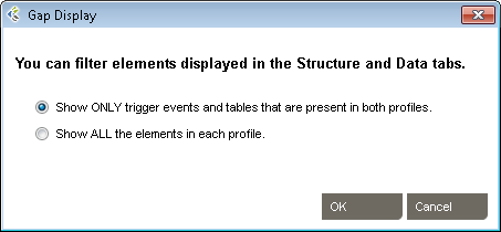
Choose Show ONLY… if you want to view the intersection set events and tables that are common to both profiles. Choose Show ALL… to show the union set.
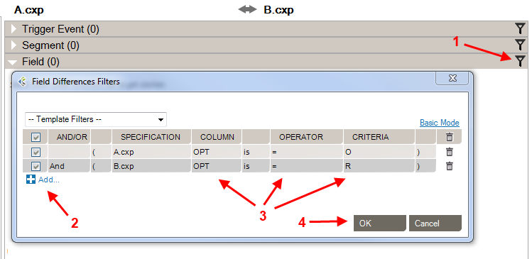
Differences Filters are used to show differences that match some specific criteria. In other words, to discard the differences which doesn’t match these criteria.
This can be used, for instance, to show only differences where the Field is Required in the Receiving Application but Optional (or Missing) in the Sending Application.
If a section contains active filters, the filter button will be shown as a full filter ![]() .
.
| Source: | Select the side from which you want to perform a filter. |
| Column: | Select the column from which you want to get the value to be compared. |
| Is/Is Not: | Include/Exclude differences that match the filter. |
| Operator: | Select the operator that you want the criteria and the column’s value to match. |
| Criteria: | Enter the criteria that you want to compare with the column’s value. |
| Checkbox: | Activate or deactivate filter (toggle on or off). |
| And/Or: | AND: applies both these filters. OR: applies either of these filters. |
| Parentheses: | Used for nested filters. |
| = | Covers values with an exact match to this data (this is like putting quotation marks around a search engine query) |
| > | Greater than. Covers filtering on numeric values. |
| >= | Greater than or equal to. Covers filtering on numeric values. |
| < | Less than. Covers filtering on numeric values. |
| <= | Less than or equal to. Covers filtering on numeric values. |
| containing | Covers messages that include this value. |
| present | Looks for the presence of a particular column. |
| empty | Looks for an unpopulated column. |
| matching regex | Use .NET regular expression syntax to build filters. For advanced users with programming backgrounds. Learn more about regular expressions here:
|
| in | Builds a filter on multiple data values rather than just one value. |
| = Other Specification Value | Exact match to the other profile’s column value. |
| > Other Specification Value | Greater than the other profile’s column value. Covers filtering on numeric values. |
| >= Other Specification Value | Greater than or equal to the other profile’s column value. Covers filtering on numeric values. |
| < Other Specification Value | Less than the other profile’s column value. Covers filtering on numeric values. |
| <= Other Specification Value | Less than or equal to the other profile’s column value. Covers filtering on numeric values. |
While editing your filters, you can switch between Basic and Advanced Mode. Advanced Mode shows advanced settings for your filters. These settings help in the construction of more complex filters using AND/OR operators and parentheses for nesting. Otherwise, each filter will be applied one after the other.
If your filters contain advanced settings and you switch back to the Basic Mode, these settings will be lost.
Differences Filters Template are re-usable filters that can be applied to many Gap Analysis. A built-in template can be selected from the drop-down list at the top-left of the filters dialog.
You can hide a difference (Gap Analysis Result row) automatically. To do so, right-click the row you want to hide, then click “Hide [row key] difference”. This adds a new difference filter entry and hide the selected row.
Message comparison helps you compare 2 sets of messages at the data level. This is useful in several cases, such as:
To compare a set of HL7 messages:
- Go to GAP ANALYSIS, Message Comparison…
- Click the Select messages to compare… zone
- Add the messages you want to compare. Messages can come from:
File: Click Add… to add one or several files containing messages
Database: Select a database to query and from which to retrieve messages.
Integration Engine: Select an integration engine data depot (Ensemble, Rhapsody, Iguana, Mirth and others) to retrieve messages directly from the integration engine (connector required).- Do the same for the other message set, clicking the other Select messages to compare… zone on the right.
Once the comparison is complete, differences are highlighted in red and the total number of differences between messages is displayed.
For a more detailed view of a message pair or message differences, double-click the message pair you want to compare. Navigate through the tree view, field by field, to see the differences.
Click on the gray zone at the bottom of the screen to view more details about each difference. Double-clicking on a grid row helps you navigate through the differences.
By default, messages will be compared based on their position. The first message on the left is compared with the first message on the right, the second with the second and so on.
Since message files don’t always contain the same amount of messages and/or messages are not necessarily always sorted in the same order, you can configure the application to match messages based on field values. To configure the message matching criteria:
Alternatively, you can:
You may want to exclude fields from the comparison so they are simply not considered in the comparison. This allows you to ignore differences in fields you don’t need to consider.
To exclude fields from comparison:
Alternatively, you can:
It can be easier to provide a list of fields to include instead of excluding a large number of fields. The procedure is similar. In the Filter tab, be sure Include (instead of Exclude) is selected.
To set a large number of fields in one operation, use the 1-on-1 message comparison screen. For example, if you want to compare fields PID.2 to PID.13:
The comparison will refresh using the new field set.
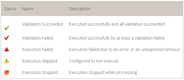
After the comparison is completed, message pairs can have one of the following statuses:
On the bottom left of the screen, the message pair count for each status is listed.
Message pairs can be shown/hidden based on their status. For instance, to hide identical messages:
Identical messages are filtered so only changed and unmatched messages are listed.
An Excel or PDF report can be generated to document the status of all messages. This report can be used, for instance, to document that the transformation code met all requirements at some point in time.
To generate this report:
The report contains:
| Automatically apply changes | If checked, the differences will be calculated each time a significant setting has changed. |
| Treat missing and empty fields as equivalent | If checked, the algorithm will consider missing and empty fields as equivalent. Ex: ‘OBX||AD|||||’ and ‘OBX||AD’ will not be flagged as different. ‘PID|||||Smith^John^’ and ‘PID|||||Smith^John’ will not be flagged as different. |
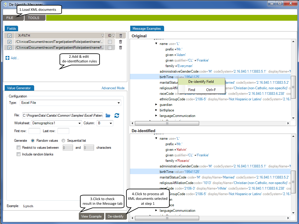
De-identification in Workgroup works as follows:
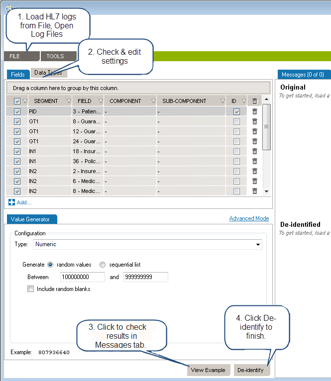
Load the HL7 message that requires de-identification:
The log is loaded in the Messages tab. The tab also indicates the number of messages in the viewing pane and the total number of messages in the file you loaded. The Original pane displays the log you loaded while the De-identified pane displays the de-identified log. The split screens scroll synchronously so that the data displayed is mirrored in the original and de-identified logs.
Resize vertically to change the quantity of data displayed in the viewing pane. Place the pointer on the line dividing the two panes and drag the window to increase or decrease its size. Click the Hide and Show buttons to hide or view panes as needed.
The fields and data types set for de-identification are highlighted in red for easy visibility.
On the left side of the screen are the de-identification settings listed under the Fields and Data Types tabs. Workgroup loads settings to cover the 18 HIPAA identifiers by default.
To add a de-identification rule under Fields or Data Types:
To remove a setting, click the trashcan at the end of the line.
Once you have created and configured all the selectors applicable to the HL7 log to be de-identified, click View Example at the bottom of the left hand panes. A preview of the de-identified log file will appear. Scroll through the log in the viewing pane to verify the potential results of the de-identification process.
Once reviewed and after applying any changes:
Once saved, a De-identification Process Report dialogue box will open asking if you wish to create a de-identification process report. Click Yes or No. If Yes is clicked, you will be prompted to choose a location to save the generated PDF and to give a name to the file. Click Save and the file will be saved to the specified location. The PDF of the De-identification Process Summary will open on your desktop for review. You can also save the file on your local computer by using Browse My Computer.
Once a set of selectors have been chosen for the de-identification of a log file, that set can be saved for reuse.
Once a log file has been opened, the saved de-identification rules can be applied by clicking Open, De-Id Rules from the drop down menu bar under File in the the top menu bar.
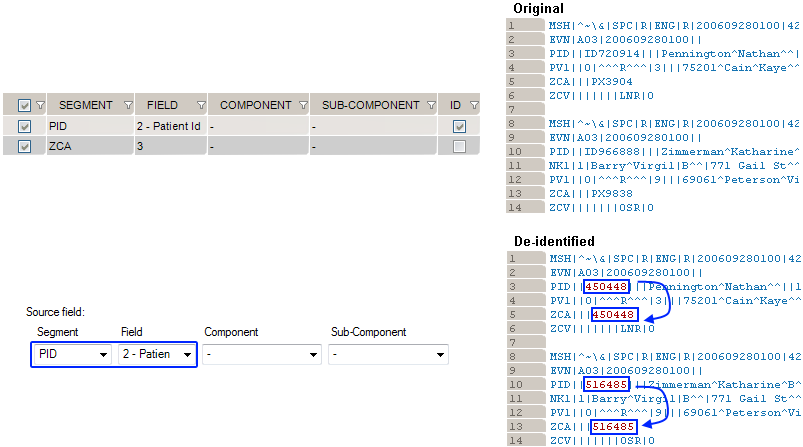
This generator replicates the value from another de-identified field.
How to use the “Copy Another Field” generator:
Example 1: copy the replacement MRN value from PID. 2 to ZCA.3
De-Identification has a number of options that can be set. From the main menu bar, click Tools, then Options. In the Options dialog box that opens, there are three categories: Reference Profile, Windows Service Settings, Delimiters and Settings.
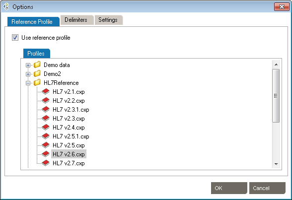
These setting allow the use of HL7 reference profiles to parse logs. Open the Reference Profile tab.
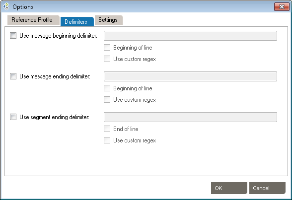
These settings allow the addition of specific delimiters to the log file to assist with manageability and readability. They include:
Click OK to save the delimiters.
Click OK to save the settings.
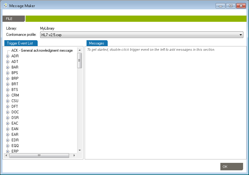
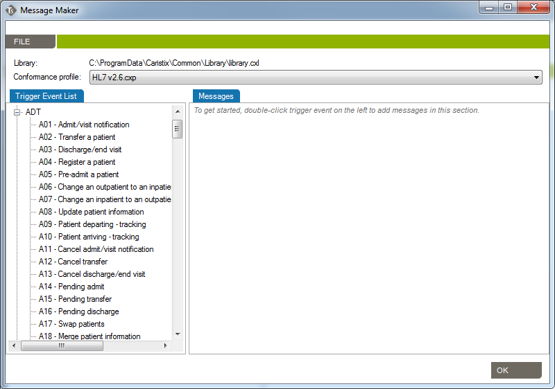
Use the Message Maker tool to create test messages to PLACE INTO a scenario or to copy to another application. The messages you generate will be based on a specific profile (an HL7 version based on the reference standard, or a profile created earlier).
The Message Editor tool lets you edit content and compare HL7 messages against a profile in order to flag conformance gaps. This is useful when you need to troubleshoot data flow in a live interface that has been documented in Caristix Workgroup.
Message Editor in Workgroup works as follow:
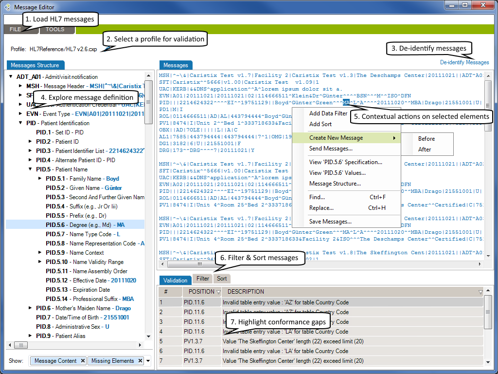
The selected HL7 messages will be loaded in the Messages tab.
Using a profile in the message editor will enable the message validation feature. The message validation will compare the HL7 messages against the profile in order to flag conformance gaps. Such gaps could come from:
Click to de-identify current messages. After the de-identification process is complete, the de-identified messages will replace your current loaded messages. Take a look at the De-identification Concepts to understand this process.
When you are analyzing a message log, you sometimes need to quickly capture an overview of a message or segment.
From there you can show/hide:
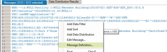
If you right-click an element in the Messsages Structure/Messages or Validation tab, a contextual menu will open. It contains the available actions for the selected element.
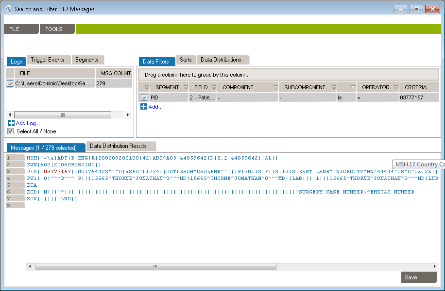
Please refer to the Search and Filter Messages documentation to work with Data Filters and Sort Queries.
The Message Editor tool lets you compare an HL7 message against a profile in order to flag conformance gaps. This is useful when you need to troubleshoot data flow in a live interface that has been documented in Caristix Workgroup. Validation tab displays conformance gaps flagged by the application.
You can save your searches and filters as a file. A Search and Filter Rules File is used to persist Data Filters, Sorts Queries and Data Distribution entries for reuse.
* You can also open a Search and Filter Rules file by right-clicking anywhere in the Data Filters, Sorts or Data Distributions section and click the “Open Search and Filter Rules…” menu.
* You can also save a Search and Filter Rules file by right-clicking anywhere in the Data Filters, Sorts or Data Distributions section and click the “Save Search and Filter Rules…” menu.
If you’ve already opened a Search and Filter Rules file, it will be added to the recent files in order to be quickly accessible. To open a recently opened file…
 Check “Use Large File mode” when loading files above 10MB in size. (This option will deactivate the Sort, Replace and Edit Message features.)
Data filters let you set up queries to find messages containing specific data such as patient IDs, names, and order types codes. Queries can filtered on specific message elements: segments, fields, components, and sub-components.
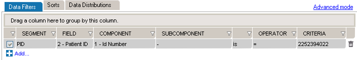
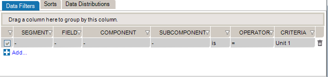
This is the recommended method for building data filters. Once you’ve built a query, you can then modify the Filter Operators to change your filter criteria.
This is an alternate method for building data filters and is helpful when applying complex filter operators.

You can also add filters from the Message Definition tree:
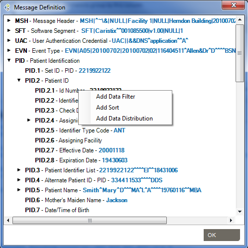
From the messages area, you can also view and edit the segment/field definition and legal values (if the field is linked to a table).
Data filter queries can be made case-sensitive. This is helpful when you need to identify data that might have been entered in all caps (JOHN SMITH) instead of title case (John Smith).
You can create filters that query the entire log, instead of a single segment or field. Simply omit the segment and field from the filter. The results in the Messages area cover all occurrences of the value you specified in the filter.
While editing your filters, you can switch between Basic and Advanced Mode. Advanced Mode shows you advanced settings for your filters. These settings help you to construct more complex filters using AND/OR operators and parentheses for nesting. Otherwise, each filter will be applied one after the other.
If your filters contains advanced settings and you switch back to the Basic Mode, these settings will be lost.
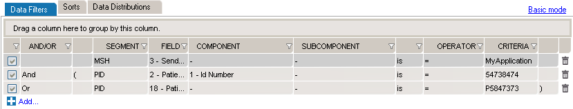
In this example, we want to create filters to get messages where (MSH.3 = MyApplication) and (PID.2.1 = 54738474) or (PID.18 = P5847373).
These filters will include the following messages:
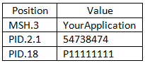
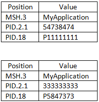 They will exclude these messages:
Data filters let you select a subset of messages from the logs you load in Workgroup. The operators let you build filter queries, ranging from simple to complex. The most basic operator set consists of the us of “is” and “=”.
![]()
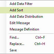
These are the default operators in the Add Data Filter command, available on the right-click dropdown menu in the Messages area.
The other data filter operators let you build sophisticated filters for analyzing the HL7 data in your log. (Learn how data filters work in the section on Working with Data Filters.)
Sort queries sort a log on a message element (segment, field, component, or subcomponent).
Sorting data is useful when you want to group messages by criteria such as patient name, date, or location.
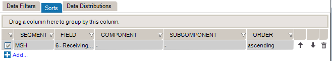
This sort on MSH 6 reorders messages by the name of the receiving facility, in this case, a patient care location.
This is the recommended method for building sorts. Once you’ve built a query this way, you can modify the Filter Operators to change your filter criteria.
This is an alternate method for building sort queries.
You can also add sort queries from the Message Definition tree. To do so:
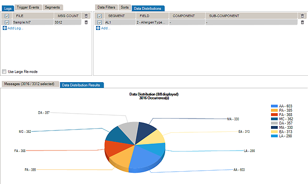
The Data Distribution feature displays the data values in a field. For instance, it helps you quickly figure out what codes are used in a specific field or how often a specific code is used.
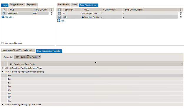
Data Distribution can also help you analyze how one field can impact other fields in terms of data and content. With Data Distribution, for example, it’s possible to get the list of lab result codes for each lab request codes within a set of sample messages.
All charts and tables can be copied and pasted to Word and Excel.
The pie chart displays the values that populate the field, as well as how often those values occur in the field.
The report displays which Allergen Type Code is sent, grouped by Sending Facilities.

You can also add data distribution fields from the Message Definition tree:
From the Data Distribution table view, you can add a Data Filter in order to find messages containing specific data:
Some interfacing technologies output non-standard message logs. In a raw state, they may be impossible to parse against an HL7-compliant standard. By adding a message prefix representing the extraneous data, you can load these logs in Pinpoint.
To add a message prefix:
You can also use message and segment ending delimiters.
Learn more about regular expressions here:
Workgroup works by parsing messages against a reference profile (or specification). The default setting is to parse against the HL7 version specified in the Version ID field of the MSH segment. However, you can also set the reference profile manually, as follows:
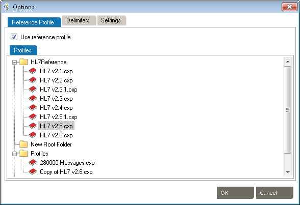
The default profile library is in %AllUsersProfile%\Application Data\Caristix\Common\Library\library.cxl. If you want to load an alternate profile library, click the Browse button.
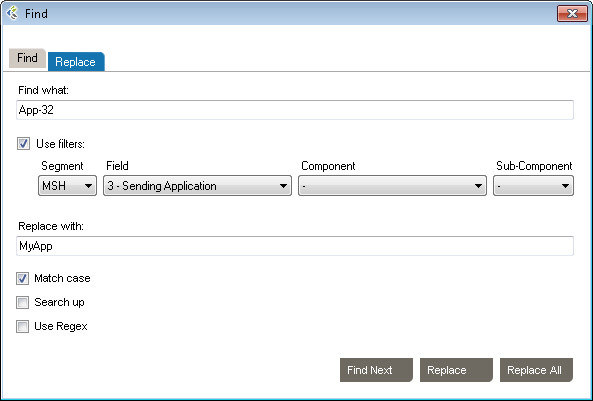
You can find and replace values in your messages. The Use filters option lets you find and replace within a field.
You can also use the Replace tab and specify a replacement value
The Message Validation tool lets you compare an HL7 log against a profile in order to flag conformance gaps. This is useful when you need to troubleshoot data flow in a live interface that has been documented in Caristix Workgroup.

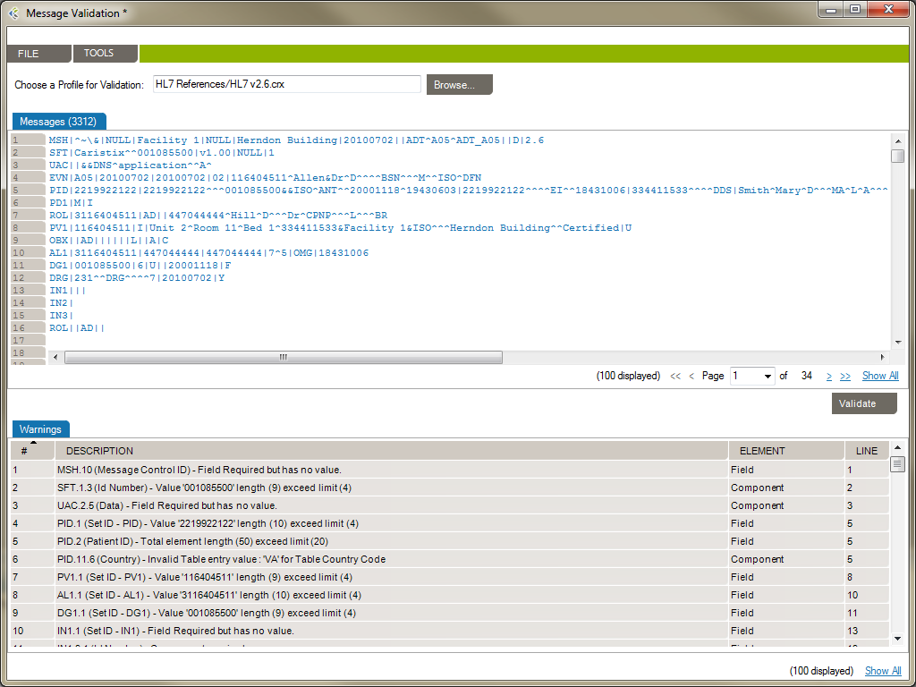
From the Message Validation tool, you can right-click any messages and open the Message Editor tool, or view the Message Definition.
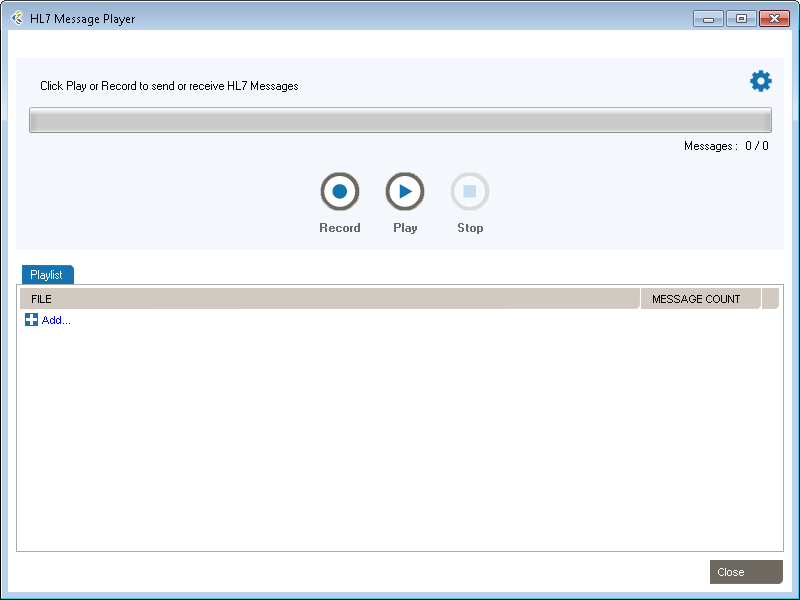
Workgroup includes Message Player, a utility you can use to send and receive HL7 messages. A few uses for Message Player:
The main features are:
To understand the de-identification concept, please read the following chapters:
De-identification in Workgroup works as follows:
The selected XML documents will be loaded in the Message Example tab. The Original pane displays the XML documents you loaded while the De-identified pane displays the de-identified XML documents. The split screens scroll synchronously so that the data displayed is mirrored in the original and de-identified panes.
The fields set for de-identification are highlighted in red for easy visibility.
On the left side of the screen are the de-identification rules listed under the Fields tab.
To add a new de-identification rule
-Or-
To remove a rule, click the trashcan at the end of the line.
To re-use existing de-identification rules
-Or-
To save your de-identification rules
-Or-
Once you have created and configured all the rules applicable to the XML documents to be de-identified, click View Example at the bottom of the left hand pane. A preview of the de-identified documents will appear. Scroll through the documents in the viewing pane to verify the potential results of the de-identification process.
Once reviewed and after applying any changes:
Caristix Workgroup helps interface analysts, engineers, and technical support team members quickly find data needed for interfacing tasks and customer service.
Search and Filter in Workgroup works as follows: 
The selected XML documents will be loaded in the Messages tab.
The fields that match your search and filter rules are highlighted in red for easy visibility.
On the right side of the screen are the search and filter rules listed under the Data Filters tab.
While editing your filters, you can switch between Basic and Advanced Mode. Advanced Mode shows you advanced settings for your filters. These settings help you to construct more complex filters using AND/OR operators and parentheses for nesting. Otherwise, each filter will be applied one after the other.
If your filters contains advanced settings and you switch back to the Basic Mode, these settings will be lost.
To add a new search and filter rule
-Or-
To remove a rule, click the trashcan at the end of the line.
To re-use existing search and filter rules
-Or-
To save your search and filter rules
-Or-
The Message Editor tool lets you edit content and compare an XML document against a profile in order to flag conformance gaps. This is useful when you need to troubleshoot data flow in a live interface that has been documented in Caristix Workgroup.
Message Editor in Workgroup works as follow:
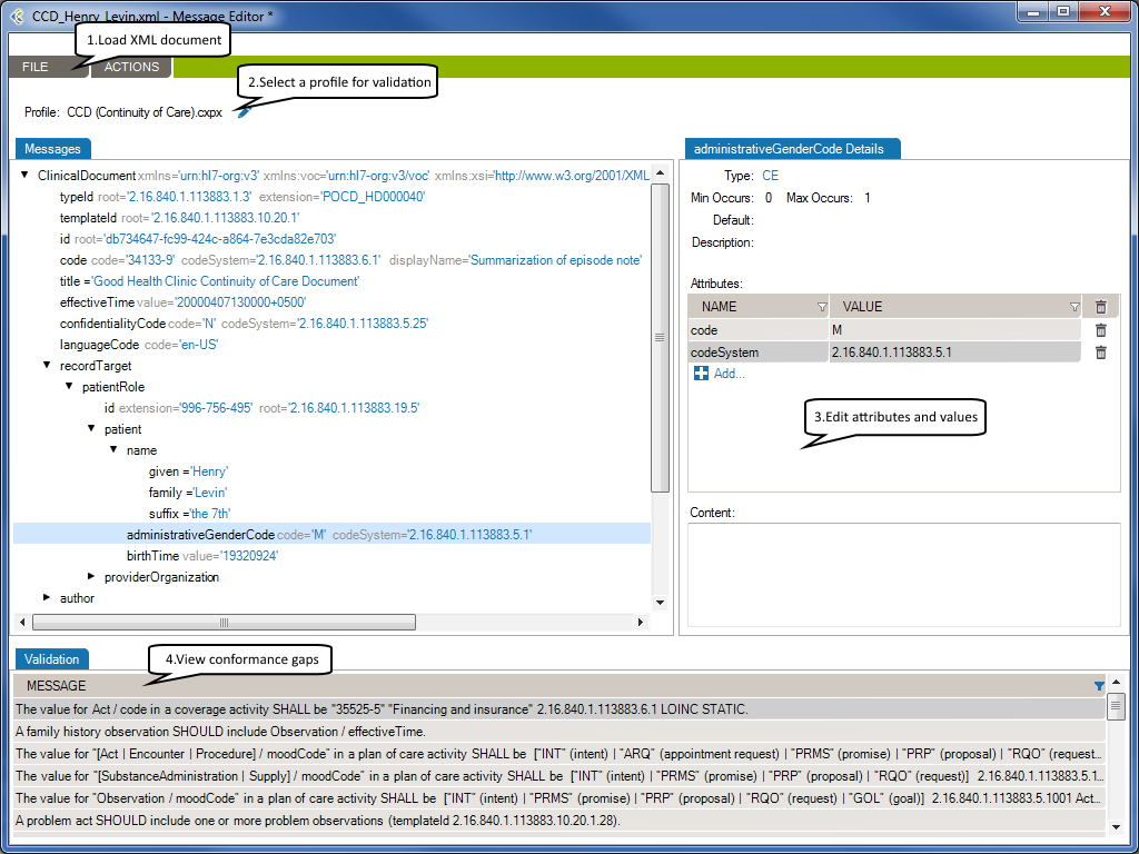
The selected XML document will be loaded in the Message tab.
Using a profile in the message editor will enable the message validation feature. The message validation will compare the XML document against the profile in order to flag conformance gaps. Such gaps could come from:
At the right side of the message tab, you will be able to edit the selected node’s attributes or content.
Using a profile will allow the message editor to provide the list of allowed attribute names and values.
If enabled, the validation tab displays conformance gaps. The tool-tip will provide you detailed information about the error.
Double-click a line to navigate through the error in your XML document.
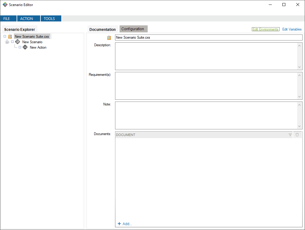
Suites are analogous to a test plan. A suite contains all of the test scenarios and workflows that you will run in order to validate that an interface works. A suite manages a collection of test scenarios (test cases).
Suites are files with the .cxs extension and are represented in the document library by the![]() icon.
icon.
A JavasScript task executes JavaScript code using our JavaScript API.
Right-click the name of the parent Action the new task will be created in, and select Add New Task –> Execute JavaScript Task.

A new Task appears under the parent Action. Edit the task name as needed. Drag and drop to change the task order.
Any valid JavaScript can be executed in this task. Simply add the code you wish to execute to the code textbox in the configuration tab. You can also use our JavaScript API to manipulate Caristix-related resources.
To return a result for validation, use the callback() method. The callback() method takes a string as an argument and sets the value returned by the task when called.
The following is an example of a JavaScript task’s code. In the example, a GET request is sent to a public FHIR server, and the resulting bundle is returned for validation.
//Create an HTTP request using the provided HTTP GET method and full resource url,
// https://daas.caristix.com/fhir/Patient.
var request = HTTP.create('GET', 'https://daas.caristix.com/fhir_r4/Patient/');
//Add the Accept header with the value application/fhir+json to the request.
request.setHeader(‘Accept’, ‘application/fhir+json’);
//Send the HTTP request.
var result = request.send();
//Obtain the HTTP result’s body – a Bundle of Patient Resources.
var body = result.body;
//Return the body.
callback(body);
Data filters and operators let you define validation rules. The operators let you build filter queries, ranging from simple to complex. The most basic operator set consists of the use of “is” and “=”.
![]()
These are the default operators in the Add Data Filter command, available on the right-click dropdown menu in the Last Result area.
The other data filter operators let you build sophisticated filters for analyzing HL7 data.
| Operator | Action |
| is | Includes messages that contain this data |
| is not | Excludes messages that contain this data |
| = | Covers messages with an exact match to this data (this is like putting quotation marks around a search engine query) |
| < | Less than. Covers filtering on numeric values. |
| <= | Less than or equal to. Covers filtering on numeric values. |
| > | Greater than. Covers filtering on numeric values. |
| >= | Greater than or equal to. Covers filtering on numeric values. |
| like | Covers messages that include this data. Covers filtering on numeric values. |
| present | Looks for the presence of a particular message building block (such as a segment, field, component, or sub-component) |
| empty | Looks for an unpopulated message building block (such as a segment, field, component, or sub-component) |
| in | Builds a filter on multiple data values in a message element rather than just one value. |
| in table | Looks if the data is in a specific table of the referenced Profile. |
| matching regex | Use .NET regular expression syntax to build filters. For advanced users with programming backgrounds. Learn more about regular expressions here:
This is also a quite good utility to hep you create complex regular expressions: |
During the validation phase, you compare transformed messages with another set of messages you already know are valid (expected message set). The highlighted differences will indicate any issues in your code or any missing transformations. This is a quick and easy way to validate that your code fulfills the requirements.
For a more detailed view of a message pair or message differences, double-click the message pair you want to compare. Navigate through the tree view, field by field, to see the differences.
Click on the gray zone at the bottom of the screen to view more details about each difference. Double-clicking on a grid row helps you navigate through the differences.
You may want to exclude fields from the comparison so they are simply not considered in the comparison. This allows you to ignore differences in fields you don’t need to consider.
To exclude fields from comparison:
Alternatively, you can:
It can be easier to provide a list of fields to include instead of excluding a large number of fields. The procedure is similar. In the Filter tab, be sure Include (instead of Exclude) is selected.
To set a large number of fields in one operation, use the 1-on-1 message comparison screen. For example, if you want to compare fields PID.2 to PID.13:
The comparison will refresh using the new field set.
After the comparison is completed, message pairs can have one of the following statuses:
On the bottom left of the screen, the message pair count for each status is listed.
Message pairs can be shown/hidden based on their status. For instance, to hide identical messages:
Identical messages are filtered so only changed and unmatched messages are listed.
This generator uses user-defined environments and allows you to map values specific to those environments for a given variable. This allows for efficient re-use of tests that are based on different development environments (Development, Production, etc.)
To use this generator, you first need to define environments to which you will map the variables. To do so, open the environment editor.
This will create default environments to work in. You can modify or delete these environments, and you can define your own environments if you want.
Now, you can create a variable of type Environment Variable and define it with the Environment Variable value generator.
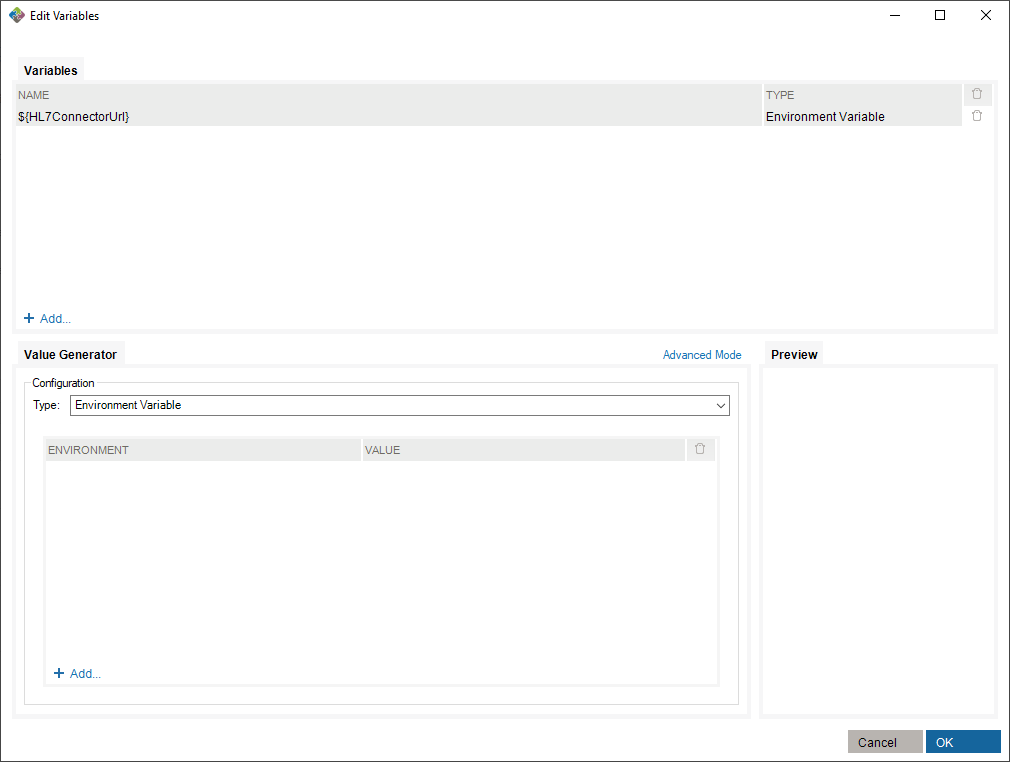
To make use of this variable, you need to assign values to existing environments in the value generator.
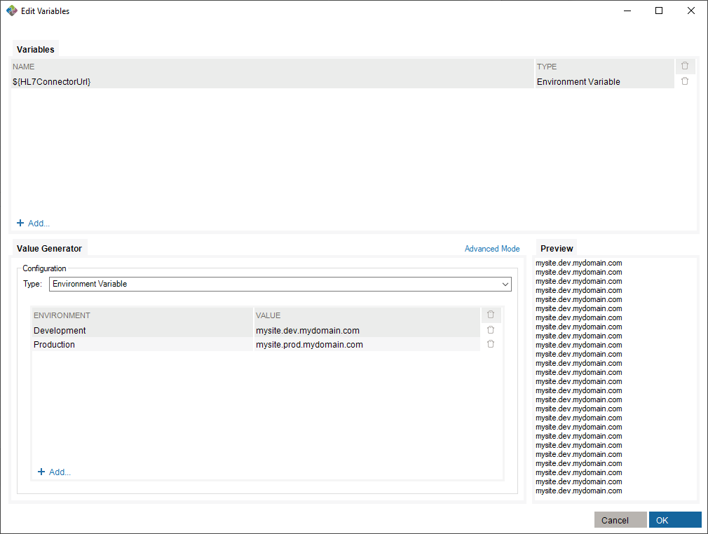
Finally, select an environment in which you run the scenario suite.
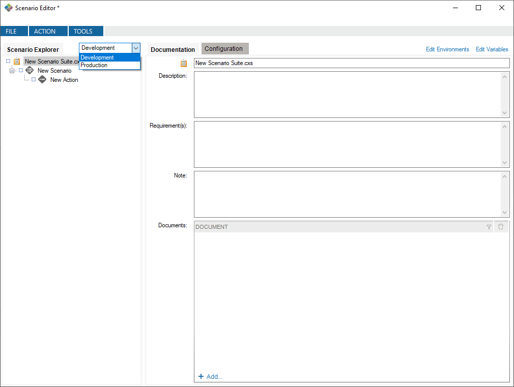
In this case, running with the Development environment will assign the value mysite.dev.mydomain.com to the ${HL7ConnectorUrl} variable.
Right-click the name of the Scenario suite, the Scenario, the Action or the Task you wish to execute. Click Run.
You can stop a test mid-way or at any time. Simply right-click on a node and select Stop.
After a test is executed, you can generate an execution report:
The generated report is an Excel document containing descriptions of the test and all results.
Use the Message Maker tool to create test messages to PLACE INTO a scenario or to copy to another application. The messages you generate will be based on a specific profile (an HL7 version based on the reference standard, or a profile created in Caristix Conformance or Caristix Workgroup software).
In most of your test automation work, you will want to use variables to populate test workflow with data. But if you need to generate HL7 messages to copy to another application, use Message Maker. Also use Message Maker if you want to use the same test data over and over again in a test scenario created with Caristix software.
Before starting to use Caristix Test, review Options to ensure your setup is appropriate for your testing and validation.
From the Main Menu, click Tools, then Options in the drop-down menu that appears.
A new Options window opens. 4 tabs are available: Logging, Reference Profile, Default Connections and Preferences.
Enabling this configuration activates internal execution log storage. Internal execution logs are actually xml files and can be open as a test suite so the test can be run again using the exact same configuration, meaning that variables are replaced with the actual values generated at run time.
This is the default profile used to validate and create new messages. Reference conformance profiles based on the HL7 standard are located here. Also, any other profile the organization may have created would be listed here too.
To know more about how to create new customized profiles (including Z-segments and customized fields), refer to the Caristix Conformance or Caristix Workgroup products.
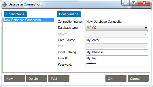
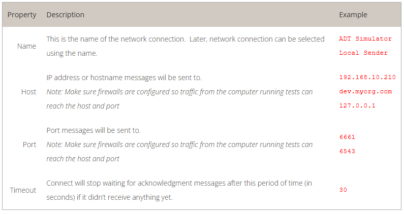
This is where connections to integration engines (or other HL7 systems) and databases are configured. Configuring a default connection for each category has a few advantages:
Caristix Test can perform tasks against a database. For instance, you can execute a SQL query to validate against expected results; or you can instantiate a variable from a data set. These settings enable you to set up database connection library and select a default database.
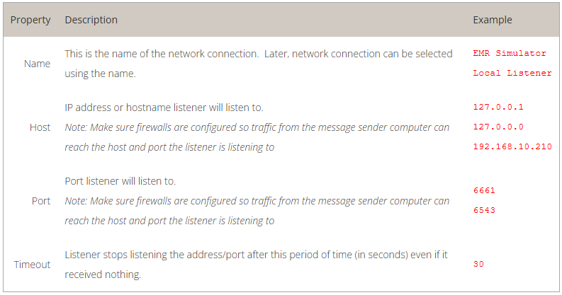
Caristix Test can interact with an integration engine or a system sending HL7 messages. These settings enable you to set up inbound network connection library and select one as the default.
Choose the default inbound network connection from the list of network connections. To configure a new network connection:
This tutorial shows you how to use Caristix software to validate transformations during a conversion project.
During projects where HL7 interfaces are ported from a legacy integration engine to a new technology, message flows (transformations, etc.) must remain the same. Actually, message content (structure and semantics) must remain the same. The challenge is to validate that the interface was ported but that the same transformations and filters still apply.
Manual validation is not a viable option for most projects. In this case, best-practice guidance is to automate repetitive, time-consuming and resource-intensive tasks.
This tutorial shows you how to set up a test suite to validate a small or a large volume of messages easily and quickly.
The process is straightforward. First, get inbound and outbound messages from your legacy engine; the outbound messages have had transformations applied to them. Second, send those original inbound messages to the new integration technology so the new transformations are applied. Finally, compare both sets of outbound messages, which should be identical. If there are any differences, it means that the transformations on each platform are not equivalent and you need to adjust the code.
Here is a step-by-step explanation.
For the purposes of this tutorial, name the suite Caristix Test Tutorial – Message Comparison
Name the scenario How To
Name the action Compare Messages
Call this new task Send initial HL7 messages.
Call it Receive transformed messages. Note: This assumes the interface will send the transformed messages back to the application. If the interface sends transformed messages to a file, use “Read HL7 file” task.
At this point, the suite skeleton is built (![]() ).
).
In this step, you’ll configure the tasks to send the initial set of messages to the new integration engine. It receives it, transform messages and sends it back to the application. The application would then be listening to receive transformed messages for validation.
Good! Let’s run the test
Once the execution is complete, each tree node will have a status icon. The expected messages should be identical to the transformed messages from the new engine. If the test works, your Expected Messages and Received Messages should be identical.
In this example, we’ll validate that MSH.9 = ADT^A01. First set up your suite, scenario, and action.

You can download the rule file for use in Caristix Workgroup or Test software.
Download the rule file (Field1 = value.cxf)
Learn more about how to import validation rules into an inbound HL7 task.
In this example, we’ll validate that values for EVN.1 and MSH.9.2 are equal.
![]()
You can download the rule file for use in Caristix Workgroup or Test software.
Download the rule file (Field1 = Field2.cxf)
Learn more about how to import validation rules into an inbound HL7 task.
In this example, let’s validate the following:


Download the rule file (Field repetition = value.cxf)
Learn more about how to import validation rules into an inbound HL7 task.
In this example, we’ll validate values for PID.3.1 in the received message is equal to PID.3.1 in the previous sent message.
![]()
You can download the rule file for use in Caristix Workgroup or Test software.
Download the rule file (Field = Field1 from outbound msg.cxf)
Learn more about how to import validation rules into an inbound HL7 task.
In this example, we’ll validate that:
In the inbound HL7 task, select the Validation tab

This illustrates the power of regular expressions.
Other quantifiers can be used
You can download the rule file for use in Caristix Workgroup or Test software.
Download the rule file (Field length.cxf)
Learn more about how to import validation rules into an inbound HL7 task.
We’ll validate that PID.19 (SSN Number) is 9 digits long.

Note: The following rule is equivalent: PID.19 is matching regex ^[0|1|2|3|4|5|6|7|8|9].*{9}$ and just list the allowed characters one by one. Feel free to change the list of characters to adapt it to your situation.
You can download the rule file for use in Caristix Workgroup or Test software.
Download the rules file (Field contains some characters only.cxf)
Learn more about how to import validation rules into an inbound HL7 task.
We’ll validate that PID.19 (SSN Number) doesn’t contain any letters or dashes.

The rule means that from the beginning of the field value (^) up to the end ($), there are no characters (^) found in the following ranges:
You can download the rule file for use in Caristix Workgroup or Test software.
Download the rules file (Field not containing some characters.cxf)
Learn more about how to import validation rules into an inbound HL7 task.
How to build a Segment/Field rule validating that a field contains a valid date. This one is sophisticated – take a look at the logic below.
We’ll validate that MSH.7 (Date/Time of message) contains a date.

This rule means that:
We think this is a nice one…
You can download the rule file for use in Caristix Workgroup or Test software.
Download the rules file (Field is a valid date.cxf)
Learn more about how to import validation rules into an inbound HL7 task.
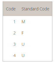

This rule tells the application to:
In other words, the validation rule loads the mapping table and returns the mapping value (M) for the initial PID.8 field (1).
Download the rules ( Field value mapping.cxf )
Learn more about how to import validation rules into an inbound HL7 task.
This tutorial explains how to build a Segment/Field rule validating that leading 0s were removed from field.
In this example. let’s validate that PID.3.1 (Patient Identifier) has no leading zeros.

This rule means that:
Download the rules file (Field has no leading 0s.cxf)
Learn more about how to import validation rules into an inbound HL7 task.
This tutorial explains how to build a Segment/Field rule validating that field has no values
In this example, we’ll validate that PV1.45 (Discharge Date/Time) is not set.

These rules mean:
Download the rules file (Field is empty.cxf)
Learn more about how to import validation rules into an inbound HL7 task.
To learn more about how to add or customize a table in a conformance profile, refer to the profile documentation

The rule returns a pass (success) if it can find the PID.8 field value in the conformance profile table. If it doesn’t, the validation fails.
Download the rules file (Field value is in table.cxf)
Learn more about how to import validation rules into an inbound HL7 task.
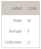
This tutorial explains how to build a Segment/Field rule validating that a field value is in a list of values.
In this example, we’ll validate that PID.8 (Administrative Sex) is equal to one of the codes in the provided list. In this case, you set the list within the validation rule. To refer to a list defined in a conformance profile, see the How to validate field is in profile code set

The rule returns a pass (success) if it can find the PID.8 field value in the provided list of values. If it doesn’t, the validation fails. Make sure each value is separated by a comma (“,”).
Download the rules file (Field is in list.cxf)
Learn more about how to import validation rules into an inbound HL7 task.
In this example, we’ll validate that the PV2 segment exists and IN1 doesn’t exist.

Download the rule file (Segment exists.cxf)
Learn more about how to import validation rules into an inbound HL7 task.
A diagram helps you represent the architecture of your systems and the different dataflows between them.

A diagram item represents a system or anything that interacts in the environment.
A dataflow represents the path taken by messages or any other type of information within the environment. It also represents the configuration needs by systems to communicate this information.
A dataflow segment is a part of a dataflow. It represents a link between two items (systems).
A dataflow segment item is one end of a dataflow segment. It represents one of the two end point between two items (systems).
From the Main Menu, click Tools, then Options in the drop-down menu that appears.
A new Options window opens.
![]()
Use the “Reset hidden tips” link to restore all hidden tips.