If you have a trial version, you will need to purchase a license to continue using Test after the end of the trial period.
A JavasScript task executes JavaScript code using our JavaScript API.
Right-click the name of the parent Action the new task will be created in, and select Add New Task –> Execute JavaScript Task.

A new Task appears under the parent Action. Edit the task name as needed. Drag and drop to change the task order.
Any valid JavaScript can be executed in this task. Simply add the code you wish to execute to the code textbox in the configuration tab. You can also use our JavaScript API to manipulate Caristix-related resources.
To return a result for validation, use the callback() method. The callback() method takes a string as an argument and sets the value returned by the task when called.
The following is an example of a JavaScript task’s code. In the example, a GET request is sent to a public FHIR server, and the resulting bundle is returned for validation.
//Create an HTTP request using the provided HTTP GET method and full resource url,
// https://daas.caristix.com/fhir/Patient.
var request = HTTP.create('GET', 'https://daas.caristix.com/fhir_r4/Patient/');
//Add the Accept header with the value application/fhir+json to the request.
request.setHeader(‘Accept’, ‘application/fhir+json’);
//Send the HTTP request.
var result = request.send();
//Obtain the HTTP result’s body – a Bundle of Patient Resources.
var body = result.body;
//Return the body.
callback(body);
Data filters and operators let you define validation rules. The operators let you build filter queries, ranging from simple to complex. The most basic operator set consists of the use of “is” and “=”.
![]()
These are the default operators in the Add Data Filter command, available on the right-click dropdown menu in the Last Result area.
The other data filter operators let you build sophisticated filters for analyzing HL7 data.
| Operator | Action |
| is | Includes messages that contain this data |
| is not | Excludes messages that contain this data |
| = | Covers messages with an exact match to this data (this is like putting quotation marks around a search engine query) |
| < | Less than. Covers filtering on numeric values. |
| <= | Less than or equal to. Covers filtering on numeric values. |
| > | Greater than. Covers filtering on numeric values. |
| >= | Greater than or equal to. Covers filtering on numeric values. |
| like | Covers messages that include this data. Covers filtering on numeric values. |
| present | Looks for the presence of a particular message building block (such as a segment, field, component, or sub-component) |
| empty | Looks for an unpopulated message building block (such as a segment, field, component, or sub-component) |
| in | Builds a filter on multiple data values in a message element rather than just one value. |
| in table | Looks if the data is in a specific table of the referenced Profile. |
| matching regex | Use .NET regular expression syntax to build filters. For advanced users with programming backgrounds. Learn more about regular expressions here:
This is also a quite good utility to hep you create complex regular expressions: |
During the validation phase, you compare transformed messages with another set of messages you already know are valid (golden message set). The highlighted differences will indicate any issues in your code or any missing transformations. This is a quick and easy way to validate that your code fulfills the requirements.
For a more detailed view of a message pair or message differences, double-click the message pair you want to compare. Navigate through the tree view, field by field, to see the differences.
Click on the gray zone at the bottom of the screen to view more details about each difference. Double-clicking on a grid row helps you navigate through the differences.
You may want to exclude fields from the comparison so they are simply not considered in the comparison. This allows you to ignore differences in fields you don’t need to consider.
To exclude fields from comparison:
Alternatively, you can:
It can be easier to provide a list of fields to include instead of excluding a large number of fields. The procedure is similar. In the Filter tab, be sure Include (instead of Exclude) is selected.
To set a large number of fields in one operation, use the 1-on-1 message comparison screen. For example, if you want to compare fields PID.2 to PID.13:
The comparison will refresh using the new field set.
After the comparison is completed, message pairs can have one of the following statuses:
On the bottom left of the screen, the message pair count for each status is listed.
Message pairs can be shown/hidden based on their status. For instance, to hide identical messages:
Identical messages are filtered so only changed and unmatched messages are listed.
This generator uses user-defined environments and allows you to map values specific to those environments for a given variable. This allows for efficient re-use of tests that are based on different development environments (Development, Production, etc.)
To use this generator, you first need to define environments to which you will map the variables. To do so, open the environment editor.
This will create default environments to work in. You can modify or delete these environments, and you can define your own environments if you want.
Now, you can create a variable of type Environment Variable and define it with the Environment Variable value generator.
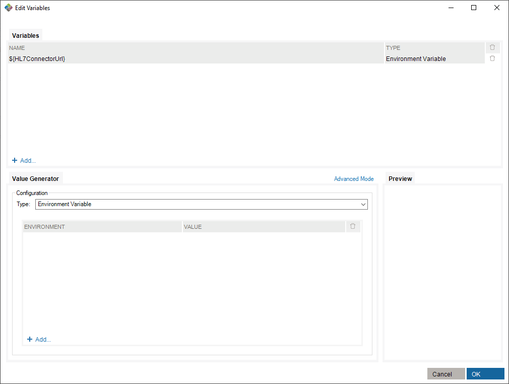
To make use of this variable, you need to assign values to existing environments in the value generator.
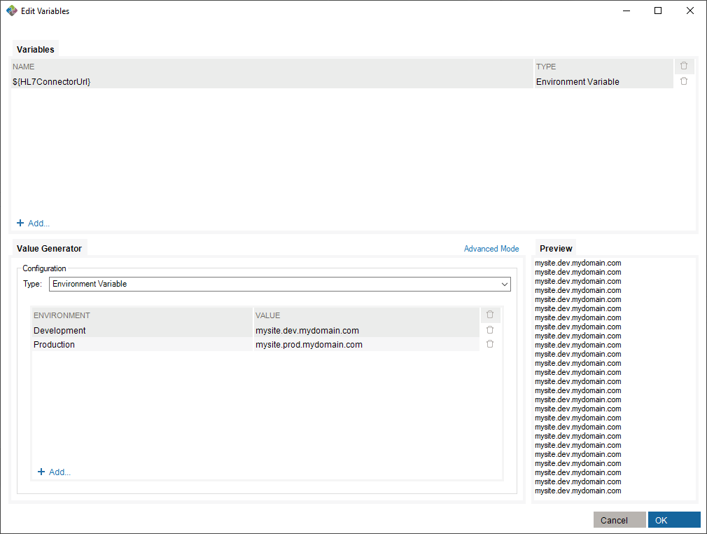
Finally, select an environment in which you run the scenario suite.
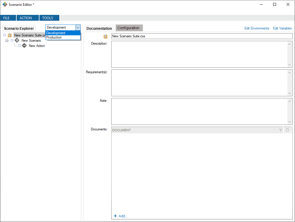
In this case, running with the Development environment will assign the value mysite.dev.mydomain.com to the ${HL7ConnectorUrl} variable.
This generator uses user-defined environments and allows you to map values specific to those environments for a given variable. This allows for efficient re-use of tests that are based on different development environments (Development, Production, etc.)
To use this generator, you first need to define environments to which you will map the variables. To do so, open the environment editor.
This will create default environments to work in. You can modify or delete these environments, and you can define your own environments if you want.
Now, you can create a variable of type Environment Variable and define it with the Environment Variable value generator.
To make use of this variable, you need to assign values to existing environments in the value generator.
Finally, select an environment in which you run the scenario suite.
In this case, running with the Development environment will assign the value mysite.dev.mydomain.com to the ${HL7ConnectorUrl} variable.
Right-click the name of the Scenario suite, the Scenario, the Action or the Task you wish to execute. Click Run.
You can stop a test mid-way or at any time. Simply right-click on a node and select Stop.
After a test is executed, you can generate an execution report:
The generated report is an Excel document containing descriptions of the test and all results.
| Column Name | Description |
| Name | The name of the suite, scenario, action or task executed. |
| Status | Status of the node. A node inherits status from its children. If a task fails, the parent action, scenario and suite status will also fail. |
| Documentation | Any documentation added to the node and last execution time. |
| Configuration | Network connection parameters that were used. Messages specified in the Configuration tab (including variables), if any. |
| Execution | Message Sent where all variables are instantiated. It’s exactly what was sent on the port. |
| Validation | Last Result Validation rules and statuses for each of them |
| Time | Execution elapse time spent on the task, action, scenario or suite |
You can also run your Scenario Suite using the command line application (TestConsole.exe) located in the Test installation folder (%PROGRAMFILES(X86)%CaristixCaristix Test or %PROGRAMFILES%CaristixCaristix Test). Simply call the application by providing the Scenario Suite to run in argument:
TestConsole.exe “C:MyScenarioSuite.cxs”
Use TestConsole.exe -h for more information.
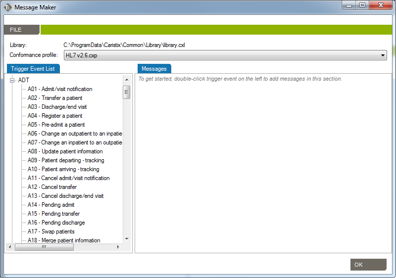
Use the Message Maker tool to create test messages to PLACE INTO a scenario or to copy to another application. The messages you generate will be based on a specific profile (an HL7 version based on the reference standard, or a profile created in Caristix Conformance or Caristix Workgroup software).
In most of your test automation work, you will want to use variables to populate test workflow with data. But if you need to generate HL7 messages to copy to another application, use Message Maker. Also use Message Maker if you want to use the same test data over and over again in a test scenario created with Caristix software.
Before starting to use Caristix Test, review Options to ensure your setup is appropriate for your testing and validation.
From the Main Menu, click Tools, then Options in the drop-down menu that appears.
A new Options window opens. 4 tabs are available: Logging, Reference Profile, Default Connections and Preferences.
Enabling this configuration activates internal execution log storage. Internal execution logs are actually xml files and can be open as a test suite so the test can be run again using the exact same configuration, meaning that variables are replaced with the actual values generated at run time.
This is the default profile used to validate and create new messages. Reference conformance profiles based on the HL7 standard are located here. Also, any other profile the organization may have created would be listed here too.
To know more about how to create new customized profiles (including Z-segments and customized fields), refer to the Caristix Conformance or Caristix Workgroup products.
This is where connections to integration engines (or other HL7 systems) and databases are configured. Configuring a default connection for each category has a few advantages:
Database ConnectionsCaristix Test can perform tasks against a database. For instance, you can execute a SQL query to validate against expected results; or you can instantiate a variable from a data set. These settings enable you to set up database connection library and select a default database.
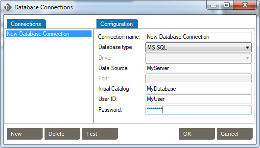
Caristix Test can interact with an integration engine or a system sending HL7 messages. These settings enable you to set up the network connection library and select one as the default.
Choose the default receiving network connection from the list of network connections. To configure a new network connection:
| Property | Description | Example |
| Name | This is the name of the network connection. Later, network connection can be selected using the name. | EMR Simulator Local Listener |
| Host | IP address or hostname listener will listen to. Note: Make sure firewalls are configured so traffic from the message sender computer can reach the host and port the listener is listening to | 127.0.0.1 127.0.0.0 192.168.10.210 |
| Port | Port listener will listen to. Note: Make sure firewalls are configured so traffic from the message sender computer can reach the host and port the listener is listening to | 6661 6543 |
| Timeout | Listener stops listening to the address/port after this period of time (in seconds) even if it did not receive anything | 30 |
Caristix Test can interact with an integration engine or a system receiving HL7 messages. These settings enable you to set up the network connection library and select one as the default.
Choose the default sending network connection from the list of network connections. To configure a new network connection:
| Property | Description | Example |
| Name | This is the name of the network connection. Later, network connection can be selected using the name. | ADT Simulator Local Sender |
| Host | IP address or hostname messages wil be sent to. Note: Make sure firewalls are configured so traffic from the computer running tests can reach the host and port | 192.168.10.210 dev.myorg.com 127.0.0.1 |
| Port | Port messages will be sent to. Note: Make sure firewalls are configured so traffic from the computer running tests can reach the host and port | 6661 6543 |
| Timeout | Connect will stop waiting for acknowledgment messages after this period of time (in seconds) if it didn’t receive anything | 30 |
This tutorial shows you how to use Caristix software to validate transformations during a conversion project.
During projects where HL7 interfaces are ported from a legacy integration engine to a new technology, message flows (transformations, etc.) must remain the same. Actually, message content (structure and semantics) must remain the same. The challenge is to validate that the interface was ported but that the same transformations and filters still apply.
Manual validation is not a viable option for most projects. In this case, best-practice guidance is to automate repetitive, time-consuming and resource-intensive tasks.
This tutorial shows you how to set up a test suite to validate a small or a large volume of messages easily and quickly.
The process is straightforward. First, get inbound and outbound messages from your legacy engine; the outbound messages have had transformations applied to them. Second, send those original inbound messages to the new integration technology so the new transformations are applied. Finally, compare both sets of outbound messages, which should be identical. If there are any differences, it means that the transformations on each platform are not equivalent and you need to adjust the code.
Here is a step-by-step explanation.
For the purposes of this tutorial, name the suite Caristix Test Tutorial – Message Comparison
Name the scenario How To
Name the action Compare Messages
Call this new task Send initial HL7 messages.
Call it Receive transformed messages. Note: This assumes the interface will send the transformed messages back to the application. If the interface sends transformed messages to a file, use “Read HL7 file” task.
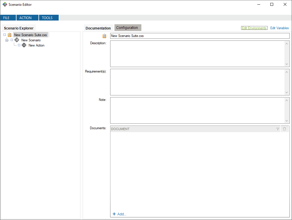
At this point, the suite skeleton is built (![]() ).
).
In this step, you’ll configure the tasks to send the initial set of messages to the new integration engine. It receives it, transform messages and sends it back to the application. The application would then be listening to receive transformed messages for validation.
Good! Let’s run the test
Once the execution is complete, each tree node will have a status icon. The expected messages should be identical to the transformed messages from the new engine. If the test works, your Expected Messages and Last Messages should be identical.
| Status | Name | Description |
| | Validation Succeeded | Executed successfully and all validation succeeded |
| Validation Failed | Executed successfully by at least a validation failed | |
| Execution Failed | Execution failed due to an error or an unexpected timeout | |
| Execution Skipped | Configured to not execute | |
| Execution Stopped | Execution stopped while processing |
In this example, we’ll validate that MSH.9 = ADT^A01. First set up your suite, scenario, and action.

You can download the rule file for use in Caristix Workgroup or Test software.
Download the rule file (Field1 = value.cxf)
Learn more about how to import validation rules into an inbound HL7 task.
In this example, we’ll validate that values for EVN.1 and MSH.9.2 are equal.
![]()
You can download the rule file for use in Caristix Workgroup or Test software.
Download the rule file (Field1 = Field2.cxf)
Learn more about how to import validation rules into an inbound HL7 task.
In this example, let’s validate the following:


Download the rule file (Field repetition = value.cxf)
Learn more about how to import validation rules into an inbound HL7 task.
In this example, we’ll validate values for PID.3.1 in the received message is equal to PID.3.1 in the previous sent message.
![]()
You can download the rule file for use in Caristix Workgroup or Test software.
Download the rule file (Field = Field1 from outbound msg.cxf)
Learn more about how to import validation rules into an inbound HL7 task.
In this example, we’ll validate that:
In the inbound HL7 task, select the Validation tab

This illustrates the power of regular expressions.
Other quantifiers can be used
You can download the rule file for use in Caristix Workgroup or Test software.
Download the rule file (Field length.cxf)
Learn more about how to import validation rules into an inbound HL7 task.
We’ll validate that PID.19 (SSN Number) is 9 digits long.

Note: The following rule is equivalent: PID.19 is matching regex ^[0|1|2|3|4|5|6|7|8|9].*{9}$ and just list the allowed characters one by one. Feel free to change the list of characters to adapt it to your situation.
You can download the rule file for use in Caristix Workgroup or Test software.
Download the rules file (Field contains some characters only.cxf)
Learn more about how to import validation rules into an inbound HL7 task.
We’ll validate that PID.19 (SSN Number) doesn’t contain any letters or dashes.

The rule means that from the beginning of the field value (^) up to the end ($), there are no characters (^) found in the following ranges:
You can download the rule file for use in Caristix Workgroup or Test software.
Download the rules file (Field not containing some characters.cxf)
Learn more about how to import validation rules into an inbound HL7 task.
How to build a Segment/Field rule validating that a field contains a valid date. This one is sophisticated – take a look at the logic below.
We’ll validate that MSH.7 (Date/Time of message) contains a date.

This rule means that:
We think this is a nice one…
You can download the rule file for use in Caristix Workgroup or Test software.
Download the rules file (Field is a valid date.cxf)
Learn more about how to import validation rules into an inbound HL7 task.
This tutorial explains how to build a Segment/Field rule validating that a field contains a valid phone number.
In this example, we’ll validate that PID.13 (Phone Number – Home) contains a phone number.

This rule means that:
Download the rules file (Field is a valid phone number)
Learn more about how to import validation rules into an inbound HL7 task.
This tutorial explains how to build a Segment/Field rule validating that a field transformation is based on a mapping table.
In this example, we’ll validate that PID.8 (Administrative Sex) is transformed following this mapping table:
| Code | Standard Code |
| 1 | M |
| 2 | F |
| 3 | U |
| 4 | U |

This rule tells the application to:
In other words, the validation rule loads the mapping table and returns the mapping value (M) for the initial PID.8 field (1).
Download the rules ( Field value mapping.cxf )
Learn more about how to import validation rules into an inbound HL7 task.
This tutorial explains how to build a Segment/Field rule validating that leading 0s were removed from field.
In this example. let’s validate that PID.3.1 (Patient Identifier) has no leading zeros.

This rule means that:
Download the rules file (Field has no leading 0s.cxf)
Learn more about how to import validation rules into an inbound HL7 task.
This tutorial explains how to build a Segment/Field rule validating that field has no values
In this example, we’ll validate that PV1.45 (Discharge Date/Time) is not set.

These rules mean:
Download the rules file (Field is empty.cxf)
Learn more about how to import validation rules into an inbound HL7 task.
This tutorial explains how to build a Segment/Field rule validating that a field value is in a predefined code set.
In this example, we’ll validate that PID.8 (Administrative Sex) is equal to one of the codes in the following table. The table is preset in a conformance profile.
| Label | Code |
| Male | M |
| Female | F |
| Unknown | U |
To learn more about how to add or customize a table in a conformance profile, refer to the profile documentation

The rule returns a pass (success) if it can find the PID.8 field value in the conformance profile table. If it doesn’t, the validation fails.
Download the rules file (Field value is in table.cxf)
Learn more about how to import validation rules into an inbound HL7 task.
This tutorial explains how to build a Segment/Field rule validating that a field value is in a list of values.
In this example, we’ll validate that PID.8 (Administrative Sex) is equal to one of the codes in the provided list. In this case, you set the list within the validation rule. To refer to a list defined in a conformance profile, see the How to validate field is in profile code set

The rule returns a pass (success) if it can find the PID.8 field value in the provided list of values. If it doesn’t, the validation fails. Make sure each value is separated by a comma (“,”).
Download the rules file (Field is in list.cxf)
Learn more about how to import validation rules into an inbound HL7 task.
In this example, we’ll validate that the PV2 segment exists and IN1 doesn’t exist.

Download the rule file (Segment exists.cxf)
Learn more about how to import validation rules into an inbound HL7 task.